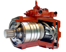
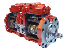
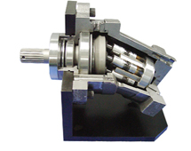
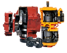
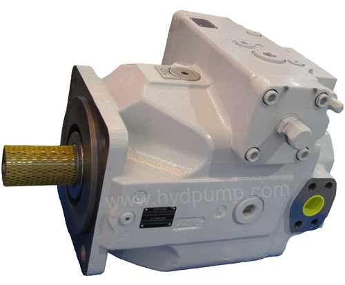
Brueninghaus Hydromatik Rexroth A4VSO Pump
Series: 10, 22, 30. With open circuit
Nominal pressure 5100 psi (350 bar).
Peak pressure 5800 psi (400 bar)
Hydraulic axial piston pump A4VSO71, A4VSO125, A4VSO180, A4VSO250, A4VSO355, A4VSO500, A4VSO750, A4VSO1000
Figure :
– Swash plate design
– Infinitely variable displacement
– Good self priming suction characteristics
– Continuous operating pressure of 5100 psi (350 bar)
– Low noise level
– Low power to weight ratio
– Drive shaft able to accept axial and radial loading
– Excellent service life
– Compact modular design
– Short control times
– Over-center design (swallow circuits)
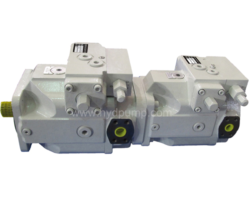
– Through drive and pump combinations possible
– Swivel angle indicator standard
– Installation positional optional
– Interchangeable with original Rexroth pump of same model
Ordering code:
|
|
(A)A4VS
|
|
O
|
500
|
DR
|
/
|
30
|
--
|
R
|
P
|
P
|
A
|
13
|
NOO
|
|
1
|
2
|
3
|
4
|
5
|
6
|
|
7
|
|
8
|
9
|
10
|
11
|
12
|
13
|
More explanation:
1- Fluid : Blank= Mineral oil
E= HF-Fluids (except Skydrol)
2- Version: AA4VS = SAE version, Swash plate design, variable
A4VS= Metric version, Swash plate design, variable
3- Axial piston unit: Blank= Without charging pump
L= With impeller, only for port option 25
4- Operation model: Pump, closed circuit
5- Size: A4VSO71, A4VSO125, A4VSO180, A4VSO250, A4VSO355, A4VSO500, A4VSO750, A4VSO1000 (cm3/rev.)
A4VSO355, A4VSO500 (cm3/rev.)
6- Control device: DR=Constant pressure control
DR=Constant pressure control
DRG=Remote control
LR=Const. Power control with hyperbolic curve
MA=Manual control
EO=Hydraulic control, with proportional valve
HD=Hydraulic control, pilot pressure dependent
7- Series: 10, 22, 30
8- Direction of rotation: R= right. L= left (Viewed on shaft end)
9- Seals: P= NBR (Nitrile rubber to DIN ISO 1629) with shaft seal FPM
V= FPM (Fluoride rubber to DIN ISO 1629)
10 Shaft end: P= Metric Parallel with key to DIN 6885
Z= Metric splined shaft per DIN 5480
S= SAE splined shaft
K= SAE parallel keyed shaft
11- Mounting flange : B= ISO 4-bolt. D= SAE 4-bolt. H= ISO 8-bolt
12- Port connections : 13= Connections B and S: SAE on side 90 degree offset, metric mounting bolts, screw
25= Connections B and S: SAE on side 90 degree offset, metric mounting bolts, flange
63= Connections B and S: SAE on side 90o offset, UNC mounting bolts
13- Through drive: N00= Without thru drive, without auxilliary pump
K31= ISO 125, 4-hole, Splined shaft 32x2x30x14x9g, to accept: A4VSO/H/G 40
K33= ISO 140, 4-hole, Splined shaft 40x2x30x18x9g, to accept: A4VSO/H/G 71
K34= ISO 160, 4-hole, Splined shaft 50x2x30x24x9g, to accept: A4VSO/H/G 125
K34= ISO 160, 4-hole, Splined shaft 50x2x30x24x9g, to accept: A4VSO/G 180
K35= ISO 224, 4-hole Splined shaft 60x2x30x28x9g, to accept: A4VSO/H/G 250
K99= With through drive shaft, without hub, without adapter flange, with cover plate
Technical Data Brueninghaus Hydromatik Rexroth AA4VSO or A4VSO Pump
Table of values (theoretical values, without efficiency and tolerances; values rounded)
Nominal size
|
A4VSO71
|
A4VSO125
|
A4VSO180
|
A4VSO250
|
|
Nominal pressure
|
p N
|
bar
|
350
|
350
|
350
|
350
|
|
Maximum pressure
|
pmax
|
bar
|
450
|
450
|
450
|
450
|
|
Displacement
|
Vg max
|
cm³
|
71
|
125
|
180
|
250
|
|
Speed
|
Max. speed
|
n max
|
rpm
|
2200
|
1800
|
1800
|
1500
|
|
Flow
|
at n max
|
q V max
|
l/min
|
156
|
225
|
324
|
375
|
|
Power
|
Δ p = 350 bar
|
P max
|
kW
|
91
|
131
|
189
|
219
|
|
Torque
|
Δ p = 350 bar
|
Tmax
|
Nm
|
395
|
696
|
1002
|
1391
|
|
Weight (approx.)
|
m
|
kg
|
53
|
88
|
102
|
184
|
|
|
|
Nominal size
|
A4VSO355
|
A4VSO500
|
A4VSO750
|
A4VSO1000
|
|
Nominal pressure
|
p N
|
bar
|
350
|
350
|
350
|
350
|
|
Maximum pressure
|
pmax
|
bar
|
450
|
450
|
450
|
450
|
|
Displacement
|
Vg max
|
cm³
|
355
|
500
|
750
|
1000
|
|
Speed
|
Max. speed
|
n max
|
rpm
|
1500
|
1320
|
-
|
1000
|
|
Flow
|
at n max
|
q V max
|
l/min
|
533
|
660
|
-
|
1000
|
|
Power
|
Δ p = 350 bar
|
P max
|
kW
|
311
|
385
|
525
|
583
|
|
Torque
|
Δ p = 350 bar
|
Tmax
|
Nm
|
1976
|
2783
|
4174
|
5565
|
|
Weight (approx.)
|
m
|
kg
|
207
|
320
|
460
|
605
|
Control devices
DR Pressure control: The DR pressure control serves to maintain a constant pressure in a hydraulic system within the control range of the pump. The pressure can be sleeplessly set on the control valve (setting range 20 to 350 bar).
Optional: with remote-controllable pressure control (DRG)
DP Pressure control for parallel operation
Suitable for pressure control of multiple A4VSO axial piston units in parallel operation.
Optional: Flow control (DPF)
FR Flow control
Maintaining a constant flow in a hydraulic system.
Optional: With remote-controllable pressure control (FRG), no connection from XF to the tank (FR1, FRG1)
DFR Pressure and flow control
This controller keeps the flow of the pump constant even under changing operating conditions. A mechanically adjustable pressure controller overrides the flow control.
Optional: No connection from XF to the tank (DFR1)
LR2 Power control with hyperbolic characteristic
The hyperbolic power control keeps the specified drive power constant at the same drive speed.
Optional: with pressure control (LR2D), remote-controllable pressure control (LR2G); with flow control (LR2F, LR2S); with hydraulic stroke limiter (LR2H); with mechanical stroke limiter (LR2M); with hydraulic two-point control (LR2Z); with electric relief valve as start assistance (LR2Y).
LR3 Power control with remote-controllable power characteristic
This hyperbolic power control keeps the specified drive power constant, whereby the power characteristic can be controlled remotely.
Optional: with pressure control (LR3D), remote-controllable pressure control (LR3G); with flow control (LR23, LR3S); with hydraulic stroke limiter (LR3H); with mechanical stroke limiter (LR3M); with hydraulic two-point control (LR3Z); with electric relief valve as start assistance (LR3Y).
LR2N and LR3N Hydraulic control, pilot pressure related
With overriding power control. The displacement is increased in proportion to the pilot pressure in PSt .
The additional hyperbolic power control overrides the pilot pressure signal and keeps the specified drive power constant.
Optional:
remote controllable power characteristic (LR3N); with pressure control (LR.DN), remote controllable pressure control (LR.GN); with electric pilot pressure specification (LR.NT).
MA Manual control
The displacement is sleeplessly adjustable via a hand wheel.
EM Electric motorized control
The displacement is sleeplessly controlled via an electric variable motor. With a programmed sequence control, various intermediate displacements can be selected by means of built-on limit switches or a potentiometer for swivel-angle feedback.
HD Hydraulic control, pilot pressure related
Steeples adjustment of the pump displacement according to the pilot pressure. The control is proportional to the specified pilot pressure set point.
Optional:
Control characteristics (HD1, HD2, HD3); with pressure control (HD.B), remote controllable pressure control (HD.GB); with power control (HD1P); with electric pilot pressure specification (HD1T)
HM1/2 Hydraulic control, volume related
The pump displacement is sleeplessly adjustable depending on the flow of pilot fluid in ports X1 and X2.
Application: 2-point switching. Base device for servo or proportional controls
HS, HS4 Control system with servo or proportional valve
The displacement is sleeplessly controlled via a servo or proportional valve and electric swivel-angle feedback. Electrically or electronically controllable.
Optional: with servo valve (HS); with proportional valve (HS4); with short-circuit valve (HSK, HS4K, HS4KP); without valves (HSE, HS4E); suitable for tank installation (HS4M). The HS4P control system is equipped with mounted pressure transducer, which means that it can be used for electric pressure and power control.
Control system EO1/2
The displacement is sleeplessly controlled via a servo or proportional valve and electric swivel-angle feedback. Electrically controllable.
Optional:
With short-circuit valve (EO1K, EO2K); without valves (EO1E, EO2E)
DS1 Speed control, secondary control
The DS1 speed control controls the secondary unit in such a way that the necessary torque is available for the required speed. When connected to a constant pressure system, this torque is proportional to the displacement and thus also proportional to the swivel angle.
DFE1 Electro-hydraulic control system
The power, pressure and swivel angle control of the A4VSO...DFE1 variable pump is performed by means of an electrically controllable proportional valve. The flow at the proportional valve determines the position of the swash plate – and thus the pump flow – via the stroke piston and the displacement pick-up. When the electric engine is switched off and the actuator system is depressurized, the pump swivels to maximum displacement by means of spring force (Vg max).
Hydraulic fluid
For extensive information on the selection of hydraulic fluids and application conditions please consult our data sheets RA 90220 (mineral oils), RA 90221 (ecologically acceptable fluids) and RA90223 (HF-fire resistant fluids).
The variable pump A4VSO or AA4VSO is suitable for operation on HF-fluids. (HFA, HFB, and HFC: EA4VSO or A4VSO....FHFD: standard version A4VSO with FKM seals) However, limitations to the technical data, according to RA 90223 must be observed.
On certain selected HFC-fluids, pump sizes 125...355, executed in accordance to RA 92053 can be operated with the same pressures and speeds as on mineral oil. On operation with HFA and HFB-fluids, limitations of the technical data must be observed according to RA 90223.
Operating viscosity range
Within the operating viscosity range between 80...450 SUS (16...100 mm2/s) the units can be operated without limitations of the technical data. In order to obtain optimum efficiency and service life, we recommend that the operating viscosity (at operating temperature) be selected in the range
Notes on the selection of hydraulic fluid
In order to select the correct fluid, it is necessary to know the operating temperature in the tank (open circuit) in relation to the ambient temperature. The hydraulic fluid should be selected so that within the operating temperature range, the viscosity lies within the optimum range; see shaded section in the selection diagram. We recommend that the higher viscosity grade is selected in each case. Temperature range (see selection diagram)
tmin = –13°F (–25° C) . tmax = 194°F (+90° C)
Example: at an ambient temperature of X° C the operating temperature in the tank is 140°F (60° C). In the optimum viscosity range (νopt ; shaded area), this corresponds to grades VG 46 or VG 68; select: VG 68.
Important: The case drain temperature is influenced by pressure and speed and is always higher than the tank temperature. However the max. Temperature at any point in the system may not exceed 194°F (90° C).
Bearing flushing
For the following operating conditions bearing flushing is required for a safe, continuous operation:
– Applications with special fluids (non mineral oils) due to limited lubricity and narrow operating temperature range
– Operation at critical conditions of temperature and viscosity with mineral oil
Flushing is recommended with vertical mounting (drive shaft facing upwards) in order to ensure lubrication of the front bearing and shaft seal.
Flushing is carried out via port „U“, located in the front flange area of the pump. The flushing fluid flows through the front bearing and leaves the pump together with the case drain flow.
Installation notes
Optional. The pump case must be filled with fluid during commissioning and remain full when operating.
In order to reduce the operating noise level, all connecting lines (suction, pressure and case drain lines) must be de-coupled from the tank, using flexible elements. The use of check valves in the case drain line must be avoided.
The case drain line must be returned directly to tank without a reduction in cross section.
Details model of Rexroth A4VSO pump
|
|
R902408952 AA4VSO180EO2/30R-PPB13N00
|
R902408444 A4VSO750HS3/30R-PZH25N00
|
|
R902408788 AA4VSO125EO2/30R-PPB13N00
|
R902408445 A4VSO1000HS3/30R-PZH25N00
|
|
R902408078 AA4VSO355DRG/30R-PPB13N00
|
R910903578 A4VSO40LR2/10R-PPB13N00
|
|
R902407830 AA4VSO355EO2/30R-PPB25N00
|
R910904555 A4VSO71LR2/10R-PPB13N00
|
|
R902405908 AA4VSO180MA/30R-PPB13N00
|
R910905022 A4VSO71LR2G/10R-PPB13N00
|
|
R902405180 AA4VSO355HD1/30R-PPB13N00
|
R910905023 A4VSO40LR2G/10R-PPB13N00
|
|
R902404305 AA4VSO125DR/30L-PPB13N00
|
R910974769 A4VSO250DR/30R-PPB13N00
|
|
R902404170 AA4VSO180DR/30R-VPB13N00
|
R910976951 A4VSO250DP/30R-PPB13N00
|
|
R902404123 AA4VSO125LR2/30R-PPB13N00
|
R910976965 A4VSO250DRG/30R-PPB13N00
|
|
R902404121 AA4VSO180DRG/30R-PPB13N00
|
R910977295 A4VSO250LR2G/30R-PPB13N00
|
|
R902404027 AA4VSO125DRG/30R-PPB13K33
|
R910978355 A4VSO250LR2N/30R-PPB13N00
|
|
R910999906 A4VSO180LR2/30R-PPB13N00
|
R910984242 A4VSO250HS3/30R-PPB13N00
|
|
R910999730 A4VSO125LR2N/30R-PPB13N00
|
R910985297 A4VSO250LR2/30R-PPB13N00
|
|
R910999125 A4VSO180DR/30R-PPB13N00
|
R910985509 A4VSO250DFR/30R-PPB13N00
|
|
R910998618 A4VSO180DFR/30R-PPB13N00
|
R910993150 A4VSO1000LR3N/30R-PZH25N00
|
|
R910985509 A4VSO250DFR/30R-PPB13N00
|
R910994306 A4VSO125DR/30R-PPB13N00
|
|
R910985297 A4VSO250LR2/30R-PPB13N00
|
R910997490 A4VSO250LR3N/30R-PPB25N00
|
|
R910978355 A4VSO250LR2N/30R-PPB13N00
|
R910998618 A4VSO180DFR/30R-PPB13N00
|
|
R910976965 A4VSO250DRG/30R-PPB13N00
|
R910998645 A4VSO125DRG/30R-PPB13N00
|
|
R910974769 A4VSO250DR/30R-PPB13N00
|
R910998987 A4VSO500HS3/30R-PPH25N00
|
|
R910904555 A4VSO71LR2/10R-PPB13N00
|
R910999045 A4VSO355HS3/30R-PPB13N00
|
|
R902404903 A4VSO125DFR/30R-PPB13N00
|
R910999125 A4VSO180DR/30R-PPB13N00
|
|
R902404123 A4VSO125LR2/30R-PPB13N00
|
R910999362 A4VSO125DR/30R-VPB13N00
|
|
R902404121 A4VSO180DRG/30R-PPB13N00
|
R910999730 A4VSO125LR2N/30R-PPB13N00
|
|
R902404123 A4VSO125LR2/30R-PPB13N00
|
R910999783 A4VSO125LR2G/30R-PPB13N00
|
|
R902404894 A4VSO125DP/30R-PPB13N00
|
R910999797 A4VSO125LR2D/30R-PPB13N00
|
|
R902404903 A4VSO125DFR/30R-PPB13N00
|
R910999867 A4VSO180LR2G/30R-PPB13N00
|
|
R902405180 A4VSO355HD1/30R-PPB13N00
|
R910999906 A4VSO180LR2/30R-PPB13N00
|
|
R902408441 A4VSO355LR3N/30R-PPB25N00
|
R910999934 A4VSO180LR2N/30R-PPB13N00
|
|
R902408442 A4VSO500LR3N/30R-PPH25N00
|
R910999125 A4VSO180DR/30R-PPB13N00
|
|
R902408443 A4VSO750LR3N/30R-PZH25N00
|
R902406427 AHAA4VSO250HD1BT/30R-PKD63K22
|
|
R902400840 AA4VSO355EO2/30R-PKD63K52
|
R902406429 AHAA4VSO250DRG/30R-PKD63K22
|
|
R902420976 A4VSO500DR/30R-PPH25N00
|
R902406430 AHAA4VSO250LR2G/30R-PKD63N00
|
For more information and technical data, please contact us.